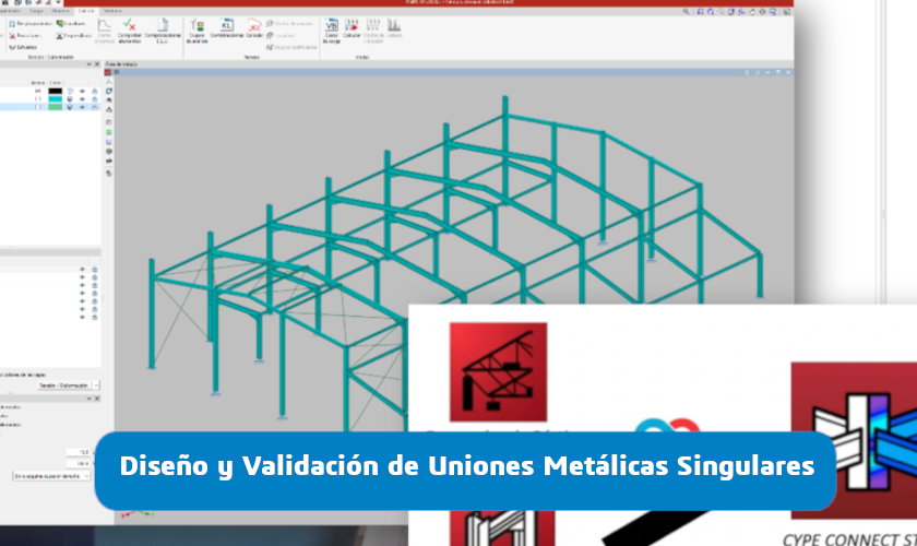
Design and Validation of Custom Steel Connections
Executive Summary: Custom steel connections are one of the most critical aspects of any structural project. While the overall structural analysis is typically resolved quickly, complex joints concentrate a significant share of technical risk, cost overruns, and approval challenges with certification bodies or end clients.
In this context, tools such as CYPE3D and CYPECONNECT enable engineers to design and analyze steel connections using advanced Finite Element Analysis (FEA), improving model accuracy and reducing technical uncertainty. The integration between both solutions also streamlines an automated workflow, allowing fast adaptation to design changes, unexpected load cases, or manufacturing constraints.
This article covers:
- How to reliably design complex steel connections
- The advantages of FEA over traditional design methods
- When to use CYPECONNECT vs. SOLIDWORKS Simulation
- How to optimize safety, documentation, and structural cost in real-world projects
Design and Validation of Custom Steel Connections
Maximizing Efficiency with CYPE3D and CYPECONNECT
1. Introduction: The Challenge of Custom Connections in Structural Projects
In day-to-day structural engineering practice, designing primary elements (beams, columns, bracing systems) is typically a straightforward process thanks to the capabilities of global analysis tools. However, the true technical and administrative bottleneck arises at the points where forces are transferred: the connections.
When a project moves away from standard catalogue joints—due to complex geometries, extreme load conditions, or on-site spatial constraints—we enter the realm of custom steel connections.
From our experience as engineering consultants at EASYWORKS, we consistently see technical offices dealing with unexpected load variations and last-minute design changes. This creates an inherent technical uncertainty when trying to represent complex joints using traditional beam-based models.
In this context, the shift toward workflows based on Finite Element Analysis (FEA) enables engineers to turn design uncertainty into a certified, optimized technical solution.
To overcome these challenges, CYPECONNECT stands out as a direct response, combining the rigor of advanced analysis with the agility required in high-level structural engineering projects.
2. CYPECONNECT Capabilities: Advanced Modeling and Analysis
CYPECONNECT is not just a connection detailing tool—it is a precision engineering solution. One of the key differentiators behind the reliability of its results is the integration of the OpenSees© calculation engine, developed at the University of California, Berkeley.

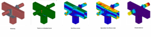
Material and Element Versatility
- Steel: Supports the modeling of rolled, built-up, cold-formed, and hollow sections. A major advantage is its ability to handle composite sections, allowing the entire member to be analyzed under a single set of internal forces.
- Concrete: Essential for the design of base plates, including the verification of the load-bearing capacity of the concrete foundation, ensuring a fully validated connection design.
3. Specialized Synergy: The CYPE3D + CYPECONNECT Workflow
The combination of CYPE3D and CYPECONNECT represents a significant step forward. This Open BIM ecosystem enables a fully integrated and automated workflow, which becomes critical when dealing with late-stage design changes.
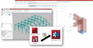
4. Advanced Design Strategies: The CYPE3D + CYPECONNECT Workflow
We classify connection solutions into typologies that have a direct impact on both structural safety and overall project cost:
a. Built-up Sections:
Used in long-span structures where standard profiles are not sufficient. Technical accuracy is ensured by linking nodes through fictitious rigid elements applied at the center of gravity, providing a more realistic load transfer model.
b. Prequalified Connections (AISC 358):
Critical in seismic design under the “strong column–weak beam” philosophy. We model solutions such as RBS (Reduced Beam Section), BEEP, and BFP, ensuring compliance with seismic performance requirements.
c. Welds and Bolted Connections:
Includes stress analysis in weld seams and full bolt verification—checking slip, bearing, and spacing requirements in accordance with design standards.
d. Base Plates and Anchors:
Focused on critical checks such as concrete cone breakout failure and the influence of reduced edge distances near foundations, which can significantly affect connection capacity.
5. Deliverables: High-Value Engineering Documentation
The quality of our engineering work is reflected in documentation designed to eliminate uncertainty:
- Design Report: Comprehensive calculation reports including detailed utilization ratios. We incorporate capacity design principles, accounting for overstrength to ensure robust and reliable performance.
- Graphical Documentation: Detailed drawings with 3D views, fabrication breakdowns, and automatically generated tagging directly extracted from the BIM model.
- EASYWORKS Recommendations: Targeted optimization proposals aimed at simplifying installation and reducing steel weight—without compromising structural integrity.
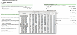
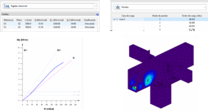
6. Rotational Stiffness and Buckling
Ignoring the real behavior of a connection can invalidate the entire structural model. At EASYWORKS, we assess both stiffness and global stability to reflect actual performance:
- Moment–Rotation Curve: Incorrectly classifying a connection as “rigid” when it behaves as “semi-rigid” leads to underestimated deflections and can compromise cladding and enclosure performance.
- Linear Buckling Analysis: We identify potential instability phenomena -such as web local buckling– before the material reaches its yield limit, enabling safer and more reliable designs.
7. SOLIDWORKS Simulation vs. CYPECONNECT
Both solutions are complementary rather than competing tools. As certified resellers and technical experts, this is our quick guideline:
Use CYPECONNECT for:
- Code compliance verification (AISC, Eurocodes, etc.).
- Management of multiple load combinations.
- Workshop fabrication drawings.
Use SOLIDWORKS Simulation for:
- Standalone mechanical components.
- Complex fittings outside standard codes.
- Fatigue and dynamic analysis.

8. EASYWORKS Services: Consulting Packages
We operate as your external engineering office, offering three levels of specialization:
BASIC
(Validation)
(Validation)
Connection checks under new scenarios (retrofits or modifications).
Inputs: Geometry + Loads.
Outputs: Code compliance utilization report.
STANDARD
(Design & Analysis)
(Design & Analysis)
Full design of custom connections from the project stage.
Inputs: Members + Internal forces.
Outputs: Complete report + Fabrication drawings.
PREMIUM
(Optimization)
(Optimization)
Iterative optimization to reduce material usage and fine-tune global stiffness.
Inputs: 3D model + Cost constraints.
Outputs: Optimized design + Technical support.
FAQs
Can you validate a connection that has already been built?
Yes. We can assess whether the utilization factor remains within acceptable limits.
What information do you need if we work with SAP2000 or ETABS?
XML files containing the “Model Definition Tables” and “Frame Forces”.
Is the report valid for a technical approval body?
Absolutely. The reports include detailed checks, calculation formulas, and full references to the applicable design standards.
Can you optimize workshop fabrication?
Yes. We streamline fabrication by reducing the number of bolts and welds without compromising safety or structural performance.
Do you need to validate a custom connection efficiently?
Our process removes friction: you send us your data, we carry out an initial review, and you receive fully validated documentation.
Get in touch with our team to request a quote for your project
or request a preliminary assessment of your most critical connection.
Trust EASYWORKS to take your safety and efficiency to the next level.